

Introduction
About the Experiment
This experiment enables a student to learn
- How to analyze logic gates
- How to express Boolean expression using logic gates
- How to check equivalence of two Boolean expressions using logic gates
- How to check equivalence of two logic circuits consisiting of multiple gates
Theory
Analysis of Logic gates using 7400(quad 2-input NAND gates),7402(quad 2-input NOR gates), 7404(HEX inverter),7408(quad 2-input AND gates),7432(quad 2-input OR gates). Diagrams of each chip are shown in Figure
 |
| Fig: 1 . 7400(quad 2 input NAND gates) Fig: 2 . 7402 (quad 2 input NOR gates) Fig: 3 . 7404(HEX inverter) Fig: 4 . 7432(quad 2-input OR gates) |
(a)AB+AC+BC=AB+AC
According to consensus theorem,the Boolean identity holds.


In the above picture both circuits are equivalent.
(b)AB+AC=(A+C)(A+B)
According to consensus theorem,the Boolean identity holds.


In the above picture both circuits are equivalent.
(c)Verify eqivalence of AND-OR and NAND-NAND structure
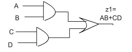

In the above picture both circuits are equivalent.
(d)Verify eqivalence of OR-AND and NOR-NOR structure


In the above picture both circuits are equivalent.
Student may be asked to wire up the network of gates shown in the above figures. They can next verify that the output of the two circuits,viz z1 and z2 should attain the same value for each of the eight possible input combinations assigned to the variables A,B,C,and D.
Objective
Aim of the Experiment
The principal objective of this experiment is to fully understand the function and use of logic gates such as
7400(quad 2-input NAND gates),7402(quad 2-input NOR gates),7404(Hex inverter) 7408(quad 2-input AND gates) and 7432(quad 2-input OR gates).
Procedure
Please follow these steps to do the experiment.
Part 1:
- At first go through the structure of 7404 Hex inverter, 7408(quad 2-input AND gates), 7432(quad 2-input OR gates).
- Next, apply a high level voltage to all the inputs A,B,C.
- Next, check that both LEDs glow. This is because both the outputs z1 and z2 attain the same value.
- Thus, AB+AC+BC=AB+AC holds for the condition A=B=C="1".
- For all the combinations of the variables A,B, and C verify that both the LEDs are glowing or not glowing. If the LED glows, it indicates that the corresponding output has reached logic 1 level. Similarly a dark LED indicates low level output voltage.

Part 2:
- At first go through the structure of 7400(quad 2-input NAND gates), 7408(quad 2-input AND gates), 7432(quad 2-input OR gates).
- Next, apply a high level voltage to inputs A,B.and apply low level voltage to the input C.
- Next, check that both LEDs glow. This is because both the outputs z1 and z2 attain the same value.
- So, the equivalence of AND-OR and NAND NAND structure can be verified.
- For all the combinations of the variables A,B and C verify that both the LEDs are glowing or not glowing. If the LED glows, it indicates that the corresponding output has reached logic 1 level. Similarly a dark LED indicates low level output voltage.

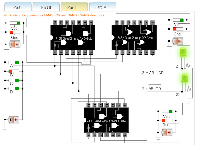
Part 3:
- At first go through the structure of 7404 Hex inverter, 7408(quad 2-input AND gates), 7432(quad 2-input OR gates), 7400(quad 2-input NAND gates).
- Next, apply a high level voltage to all the Vcc inputs and keep low level voltage to all the Gnd inputs.If Vcc and ground are not connected properly then error message will be appeared and no output will be generated.
- Next, apply a high level voltage to the inputs A,B and apply low level voltage to the input C.
- Next, check that both LEDs glow.This is because both the outputs z1 and z2 attain the same value.
- Thus, AB+AC+BC=AB+AC =(A+C)(A+B) holds for the condition A=B="1" and C=D="0"
- For all the combinations of the variables A,B and C verify that both the LEDs are glowing or not glowing. If the LED glows, it indicates that the corresponding output has reached logic 1 level. Similarly a dark LED indicates low level output voltage

Part 4:
- At first go through the structure of 7402(quad 2-input NOR gates), 7408(quad 2-input AND gates), 7432(quad 2-input OR gates).
- Next, apply a high level voltage to all the Vcc inputs and apply low level voltage to all the Gnd inputs.If Vcc and ground are not connected properly then error message will be appeared and no output will be generated.
- Next, apply a high level voltage to all the inputs A,C and apply low level voltage to the inputs B,D.
- Next, check that both LEDs glow.This is because both the outputs z1 and z2 attain the same value.
- So, the equivalence of OR-AND and NOR-NOR structure can be verified.
- For all the combinations of the variables A,B,C and D verify that both the LEDs are glowing or not glowing. If the LED glows, it indicates that the corresponding output has reached logic 1 level. Similarly a dark LED indicates low level output voltage.


MCQ
-
If a 3-input NOR gate has eight input possibilities, how many of those possibilities will result in a HIGH output?
- 1
- 2
- 7
- 8
Answer : Option ( a ) -
If a signal passing through a gate is inhibited by sending a LOW into one of the inputs, and the output is HIGH, the gate is a(n):
- AND
- NAND
- NOR
- OR
Answer : Option ( b ) -
TTL operates from __
- 9v supply
- 5v supply
- 12v supply
- 3v supply
Answer : Option ( b ) -
The output of a NOR gate is HIGH if
- all inputs are HIGH
- all inputs are LOW
- all inputs are HIGH
- all inputs are LOW
Answer : Option ( b ) -
What does the small bubble on the output of the NAND gate logic symbol mean?
- open collector output
- tristate
- The output is inverted
- none of the above
Answer : Option ( c )
