

Aim:
To design a 3-bit binary up/down counter using flip flop
Apparatus required:
IC 74LS76, Power supply, LEDs, and Function generator
Learning Objectives:
To learn to realize the functionality of sequential circuits using basic flip-flops
Theory:
A sequential circuit that goes through a prescribed sequence of states upon the application of input pulses is called a counter. The input pulses, called count pulses, maybe clock pulses. In a counter, the sequence of states may follow a binary count or any other sequence of states. Counters are found in almost all the equipment containing digital logic. They are used for counting the number of occurrences of an event and are useful for generating timing sequences to control operations in a digital system.
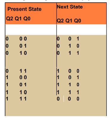
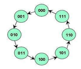 |
| State diagram of 3-bit binary up counter Present State Next State |
Procedure:
- Design the circuit as given below. Circuit diagram of 3 bit up counter
- Apply clock pulse of 1 Hz frequency and check the output on Q0, Q1 and Q2. 6. Circuit Diagram: Circuit diagram of 3 bit down counter

Circuit Diagram:
 | |
|
Observations:
 |
Results:
Learning Outcomes:
The student will be able to design a counter using flip flop.Precautions:
- Do not press the IC on breadboard until pins are aligned with pours.
- Make connection properly. There should not any short circuit in the circuit.
- Avoid the heating of IC. Provide proper clock pulse.
